- Published on
Arduino RF-Transceiver for Homekit
- Authors

- Name
- Christopher Helf
I've recently started integrating more and more devices into Homekit. Two devices have evaded my efforts so far however: remote controls for my projector screen and a light installation that my wife bought a while ago. As I'm starting to work on a larger project with Arduino's again anyways, I decided this was a good use case to get started again given I haven't worked on stuff like this forever.
Finding the right frequency
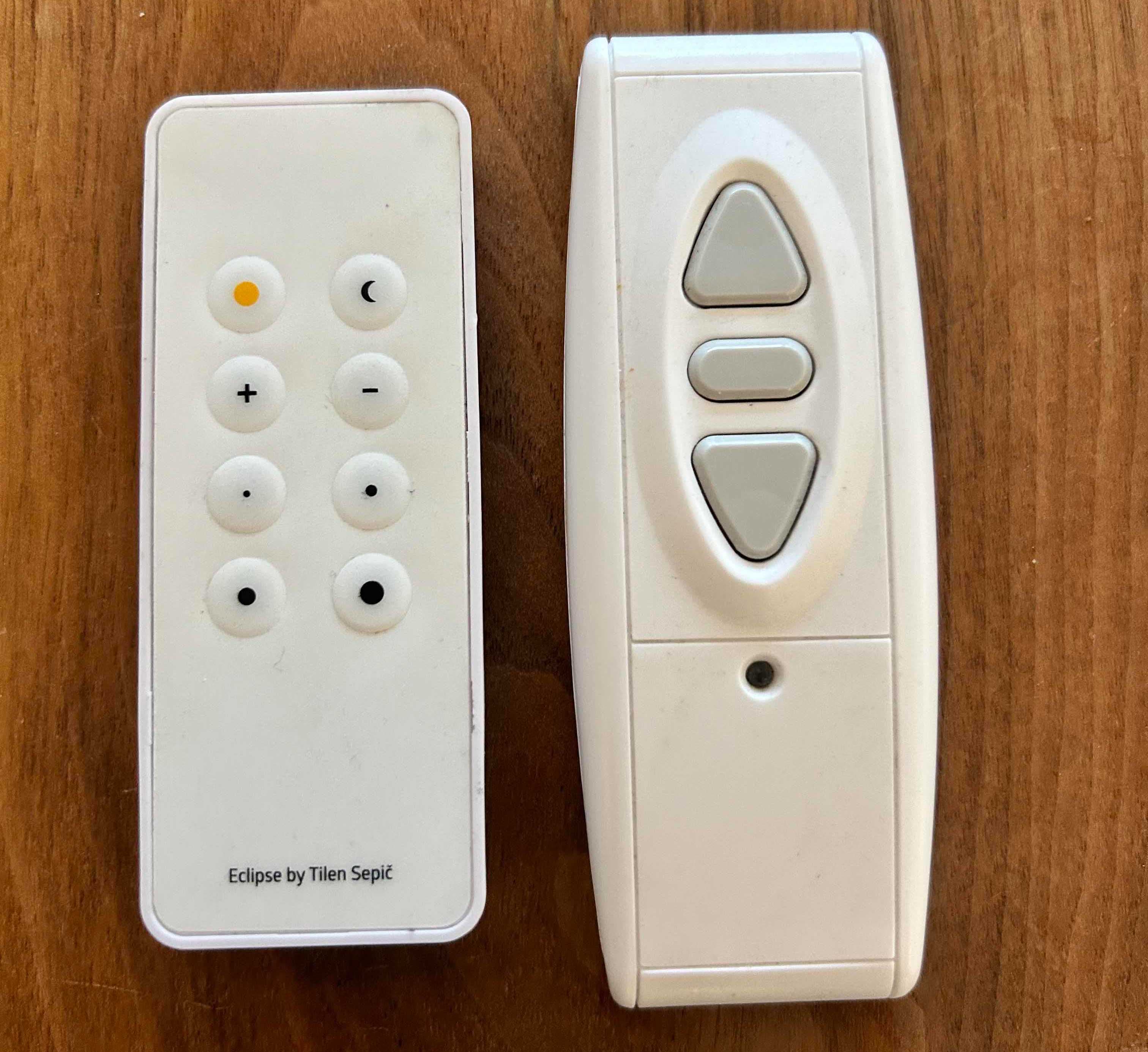
Here are the two remotes. Rather than disassembling them and checking their chips (which might not help in the end, chips usually support more than one frequency) I decided to go the sniffing route. Luckily, I had a SDR (Nooelec RTL-SDR v5 SDR) at home. A SDR (Software-Defined-Radio) is essentially a RF-Receiver that has no specific protocol decoding and can basically output raw RF signals, which is very useful to determining what these remotes are transmitting on.
My SDR happens to work perfectly with the rtl_433 library, a CLI-tool to capture and analyse signals. There is a whole section on their documentation that helps a lot in discovering foreign signals.
You can use the following commands to clone and build it (you'll need CMake).
$ git clone https://github.com/merbanan/rtl_433
$ cd rtl_433
$ mkdir build && cd build
$ cmake ..
$ make
$ cd src # Binaries are here
Now comes the fun part! The most common frequencies for these remotes are around 315Mhz, 433Mhz and 868Mhz. Plugin your SDR and run it on each of the frequences.
./rtl_433 -f 315M -S all
You don't need an antenna really for this step yet. Just place your device very close to the receiver and press the buttons on the remote. That should output a *.cu8 file. Drop it into this tool to get a visual output.
Note: rtl_433 comes with a bunch of existing protocols, -S all basically tells it to save all signals, including known ones.
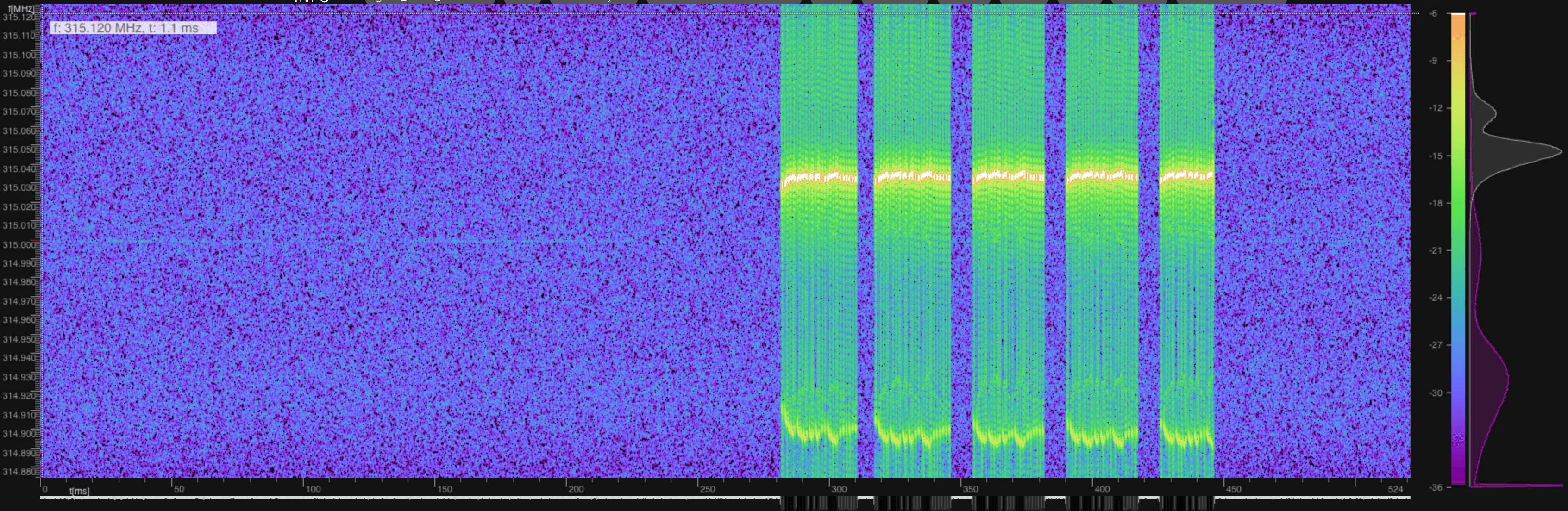
Sure enough, our signals become visible, and it happens that my remotes operate at:
- 315Mhz (light remote)
- 433Mhz (screen projector remote)
315Mhz is actually illegal in Europe ¯_(ツ)_/¯ as far as I know.
You can see where the signal has the strongest gain, and derive the frequency from that. In the image above, you can already see that the remote is sending pulses, which usually encode bits as a series of HIGHs and LOWs. Each protocol has its own variant how these are encoded (more about this later).
You can also use rtl_433 to analyse the signal directly.
./rtl_433 -f 315M -A
For my remote, this outputs something like this:
Analyzing pulses...
Total count:   82,  width: 116.20 ms		(29049 S)
Pulse width distribution:
 [ 0] count:   44,  width:  292 us [288;312]	(  73 S)
 [ 1] count:   37,  width:  860 us [856;864]	( 215 S)
 [ 2] count:    1,  width:  376 us [376;376]	(  94 S)
Gap width distribution:
 [ 0] count:   41,  width:  840 us [836;848]	( 210 S)
 [ 1] count:   37,  width:  272 us [268;276]	(  68 S)
 [ 2] count:    3,  width: 8804 us [8796;8812]	(2201 S)
Pulse period distribution:
 [ 0] count:   78,  width: 1132 us [1128;1152]	( 283 S)
 [ 1] count:    3,  width: 9096 us [9092;9100]	(2274 S)
Pulse timing distribution:
 [ 0] count:   81,  width:  284 us [268;312]	(  71 S)
 [ 1] count:   78,  width:  848 us [836;864]	( 212 S)
 [ 2] count:    1,  width:  376 us [376;376]	(  94 S)
 [ 3] count:    4,  width: 9104 us [8796;10004]	(2276 S)
Level estimates [high, low]:  15910,      5
RSSI: -0.1 dB SNR: 35.0 dB Noise: -35.2 dB
Frequency offsets [F1, F2]:    8662,      0	(+33.0 kHz, +0.0 kHz)
Guessing modulation: Pulse Width Modulation with sync/delimiter
Attempting demodulation... short_width: 292, long_width: 860, reset_limit: 8816, sync_width: 376
Use a flex decoder with -X 'n=name,m=OOK_PWM,s=292,l=860,r=8816,g=0,t=0,y=376'
[pulse_slicer_pwm] Analyzer Device
codes     : {81}88ae3fc4571fe22b8ff10, {0}0
This gives you an overview of the distribution of different timings of the signal and an estimated modulation. At this point, we don't know anything about the protocol yet. A typical RF protocol encodes 1s and 0s as a combination of HIGH and LOW pulses (e.g. 1 HIGH, 3 LOW = 1 bit) and has a synchronisation sequence. From the output above, we can only guess that the shortest pulse is around 292us, so that should be close to one HIGH pulse. You can get more information about this output by running
$ ./rtl_433 -X help
Now its time to replicate this on an Arduino.
Arduino Setup & Wiring
I had an Arduino Nano at home so that's what I'll be using. In order to receive and transmit signals, you'll also need receivers and transmitters that we can connect to it. There are really cheap ones all over the internet (and Amazon), buy ones for the frequency you need. From here on, I'll only describe the process for my remote on 433Mhz, but its the same for other frequencies (including wiring).
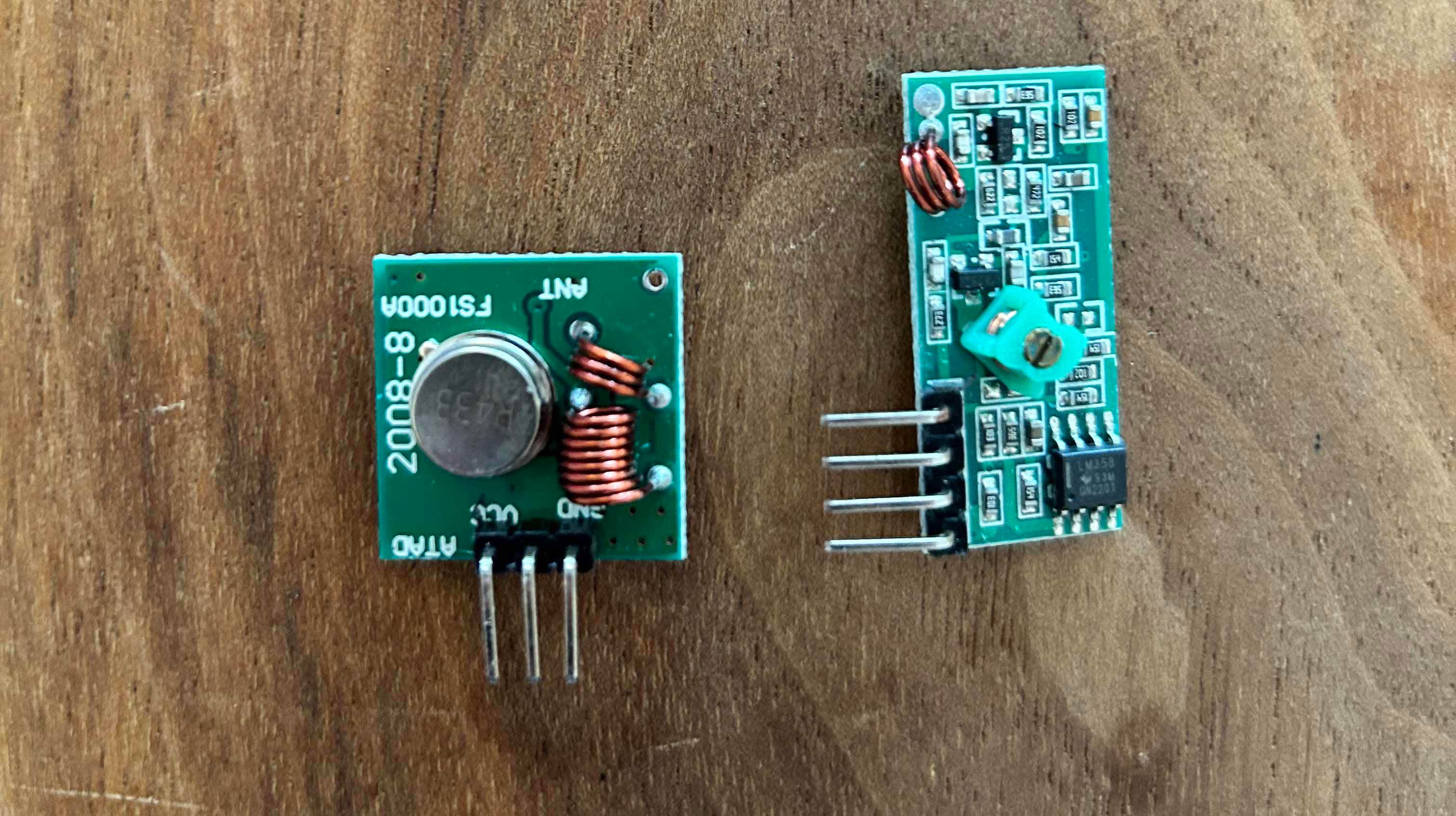
Here are the transmitter (left) and receiver (right). Next, we'll connect both transmitter and receiver to the Arduino.
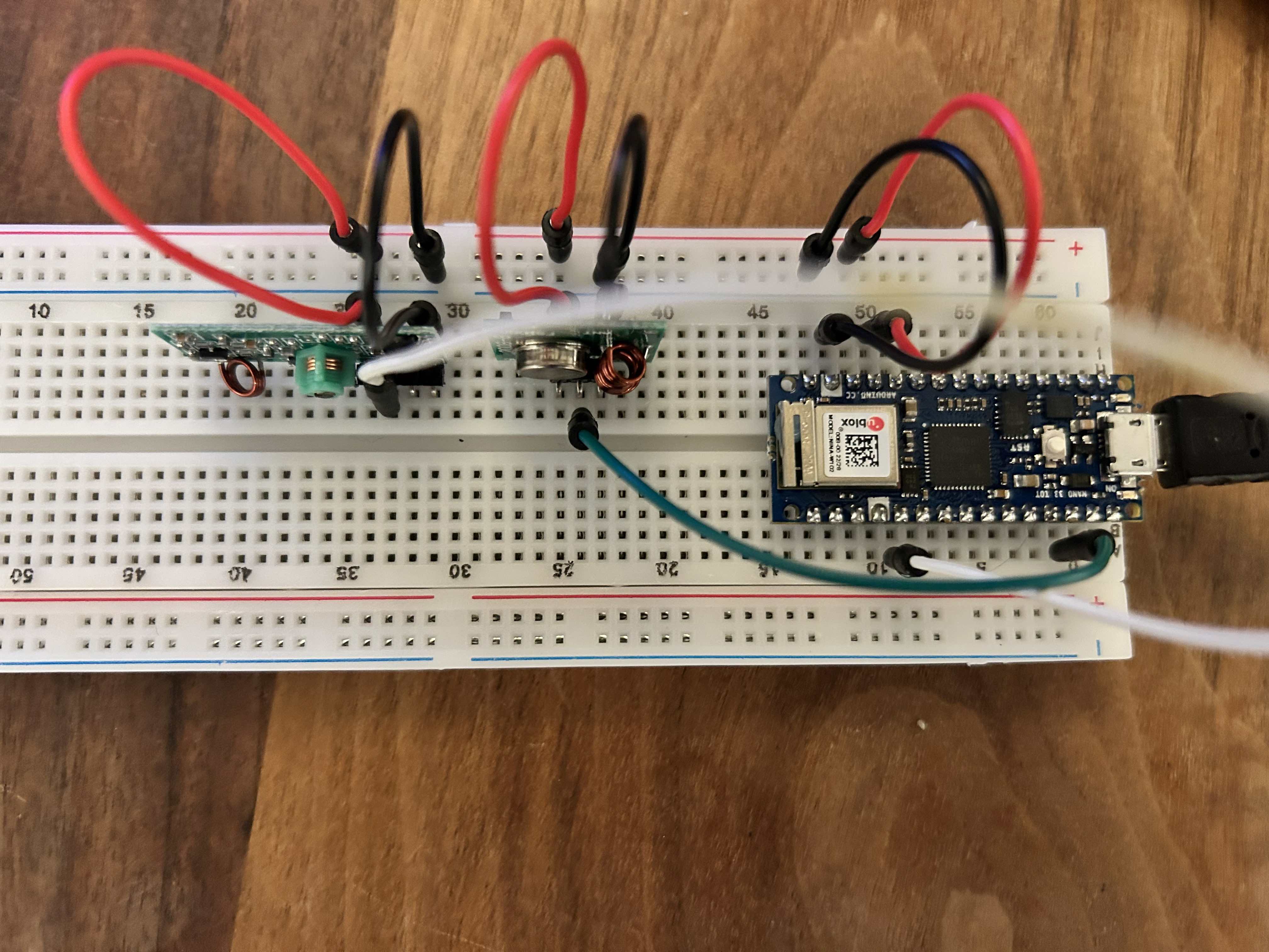
Here's the wiring setup.
VCC (both TX and RX) -> +5V
GND -> GND
RX Data Pin (Next to VCC) -> Pin D2
TX Data Pin -> Pin D10
Finding the protocol
Now that we have wired everything, its time to decode the protocols of the controls. We will be using two libraries:
The first one is a simple tool to get a raw overview of the pulses again from the signal, but this time directly from the Arduino and the components we will be using to actually transmit the signal again. The second one is a utility library to talk to common protocols and has a bunch of them already setup. Let's fire up Arduino IDE and connect our Arduino. Lets add the following code:
#include <RCSwitch.h>

RCSwitch rf_switch = RCSwitch();

#define SAMPLESIZE 500

static unsigned int timings[SAMPLESIZE];
static unsigned int pos = 0;
static unsigned long lastTime = 0;

// Pins
static int receiverPin = 2;
static int transmitterPin = 10;
static int interruptPin = 0;
static int ledPin = 13;

// Whether we are recording
static int recording = 0;

// Configuration of transmission
static int protocol = 1;
static bool shouldTransmit = 0;
static unsigned long code = 1;
static unsigned int codeLength = 24;

void setup() {
  Serial.begin(9600);

  // RX
  interruptPin = digitalPinToInterrupt(receiverPin);
  attachInterrupt(interruptPin, handleInterrupt, CHANGE);

  // TX
  rf_switch.enableTransmit(transmitterPin);
  rf_switch.setProtocol(protocol);
  rf_switch.setRepeatTransmit(3);

  // LED
  pinMode(ledPin, OUTPUT);
  digitalWrite(ledPin, LOW);
}

void loop() {
    for (int i = 5; i>0; i--) {
      Serial.print(i);
      Serial.print("... ");
      delay(900);
      digitalWrite(ledPin, HIGH);
      if (shouldTransmit) {
        rf_switch.send(code, codeLength);
      }
      delay(100);
      digitalWrite(ledPin, LOW);
    }
    Serial.println();

    detachInterrupt(interruptPin);

    int finalstate = digitalRead(receiverPin);

    char s = Serial.read();

    for (unsigned int i = pos + finalstate; i< SAMPLESIZE; i++) {
      Serial.print( timings[i] );
      Serial.print(",");
    }

    for (unsigned int i = 0; i < pos; i++) {
      Serial.print( timings[i] );
      Serial.print(",");
    }

    Serial.println("");
    Serial.println("Reset your Arduino to scan again...");

    while(true) {}

}

void handleInterrupt() {
  const long time = micros();
  timings[pos] = time - lastTime;
  lastTime = time;
  if (++pos > SAMPLESIZE-1) {
    pos = 0;
  }
}
Let's break this down step by step. First, we configure the input and output pins as in our wiring. Ignore transmission part for now, we'll get to that later. In the configured interrupt (we only monitor changes from HIGH->LOW and LOW->HIGH), we are basically writing the time deltas at each pos and then increment it. This way, we get a good overview of the pulse lenghts that occur in the signal. In the loop, we then basically print instructions to the screen for 5 seconds - during this time we can then record our signal using the remote. Finally, we print the time deltas to the serial console.
Alright, once this is done you can post the output from the serial console into this tool (keep this tab open!). Note that most remotes send the same signal multiple times, so watch out for some pattern in that graph.
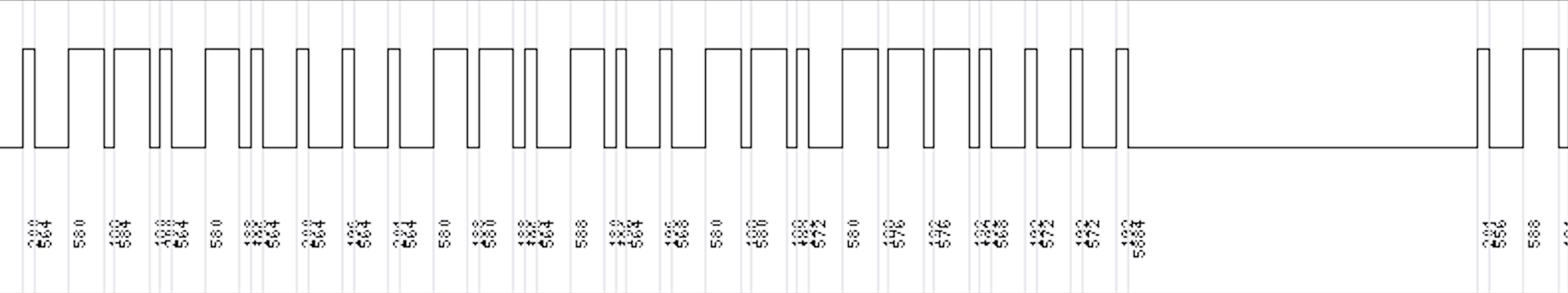
Now this is the raw signal that we need to understand and decode. Note again how HIGHs and LOWs alternate, and then the repetation of the signal with a synchronisation sequence in between. Important here is really the length of the pulse (check for the shortest pulse in the sequence), which here is roughly 200us.
Next, we will use rc-switch directly to see whether it can decode the protocol on its own.
Replace the loop function with the following:
void loop() {
  if (rf_switch.available()) {
    Serial.print("Received ");
    Serial.print( rf_switch.getReceivedValue() );
    Serial.print(" / ");
    Serial.print( rf_switch.getReceivedBitlength() );
    Serial.print("Bit ");
    Serial.print(" // ");
    Serial.print("Protocol: ");
    Serial.println( rf_switch.getReceivedProtocol() );
    digitalWrite(13, HIGH); // Toggle the onboard LED  if serial is available - Optional
    delay(1);
    digitalWrite(13, LOW);
    rf_switch.resetAvailable();
  }
}
and deploy it to the Arduino. Once its running, start pressing buttons on your remote. If you are lucky, one of the existing protocols matches the one from your remote. If not, you will need to do further digging. In my case, I had to adjust the protocol slightly to get it working. If you look into RCSwitch.cpp, you will find the following definition:
static const RCSwitch::Protocol PROGMEM proto[] = {
  { 350, {  1, 31 }, {  1,  3 }, {  3,  1 }, false },    // protocol 1
  { 650, {  1, 10 }, {  1,  2 }, {  2,  1 }, false },    // protocol 2
  { 100, { 30, 71 }, {  4, 11 }, {  9,  6 }, false },    // protocol 3
  { 380, {  1,  6 }, {  1,  3 }, {  3,  1 }, false },    // protocol 4
  { 500, {  6, 14 }, {  1,  2 }, {  2,  1 }, false },    // protocol 5
  { 450, { 23,  1 }, {  1,  2 }, {  2,  1 }, true },     // protocol 6 (HT6P20B)
  { 150, {  2, 62 }, {  1,  6 }, {  6,  1 }, false },    // protocol 7 (HS2303-PT, i. e. used in AUKEY Remote)
  { 200, {  3, 130}, {  7, 16 }, {  3,  16}, false},     // protocol 8 Conrad RS-200 RX
  { 200, { 130, 7 }, {  16, 7 }, { 16,  3 }, true},      // protocol 9 Conrad RS-200 TX
  { 365, { 18,  1 }, {  3,  1 }, {  1,  3 }, true },     // protocol 10 (1ByOne Doorbell)
  { 270, { 36,  1 }, {  1,  2 }, {  2,  1 }, true },     // protocol 11 (HT12E)
  { 320, { 36,  1 }, {  1,  2 }, {  2,  1 }, true },      // protocol 12 (SM5212)
};
This is where protocols are defined. Lets check e.g. for protocol 1 (as described in here):
350 = Pulse length
{3,25} = Synchronisation bit represented by three HIGH pulses followed by 25 LOW pulses
{1,3} = 0-bit represented by one HIGH pulse, followed by three LOW pulses.
{3,1} = 1-bit represented by three HIGH pulses, followed by one LOW pulse
False = Whether to invert the signal.
So for our protocol, depending on whether on protocol generically matches or not, we either need to create a completely new one, or copy-paste an existing one and modify its parameters. The best process that I found for doing this is to have a transmitter and receiver running on the Arduino at the same time, and outputting the values for comparison while adjusting the individual values.
In my case, I created a new protocol for my remotes and guessed its values roughly based on what I had from my scanner and rc-switch so far. Lets go back to the original code and modify the following parameters:
static int protocol = 13; // The newly added protocol
static bool shouldTransmit = true; // We will now transmit the signal ourself
static unsigned long code = 17819712; // Code we have from rc-switch
static unsigned int codeLength = 24; // 24 bits
Fire up the arduino and copy paste the values into here again.
Final assembly
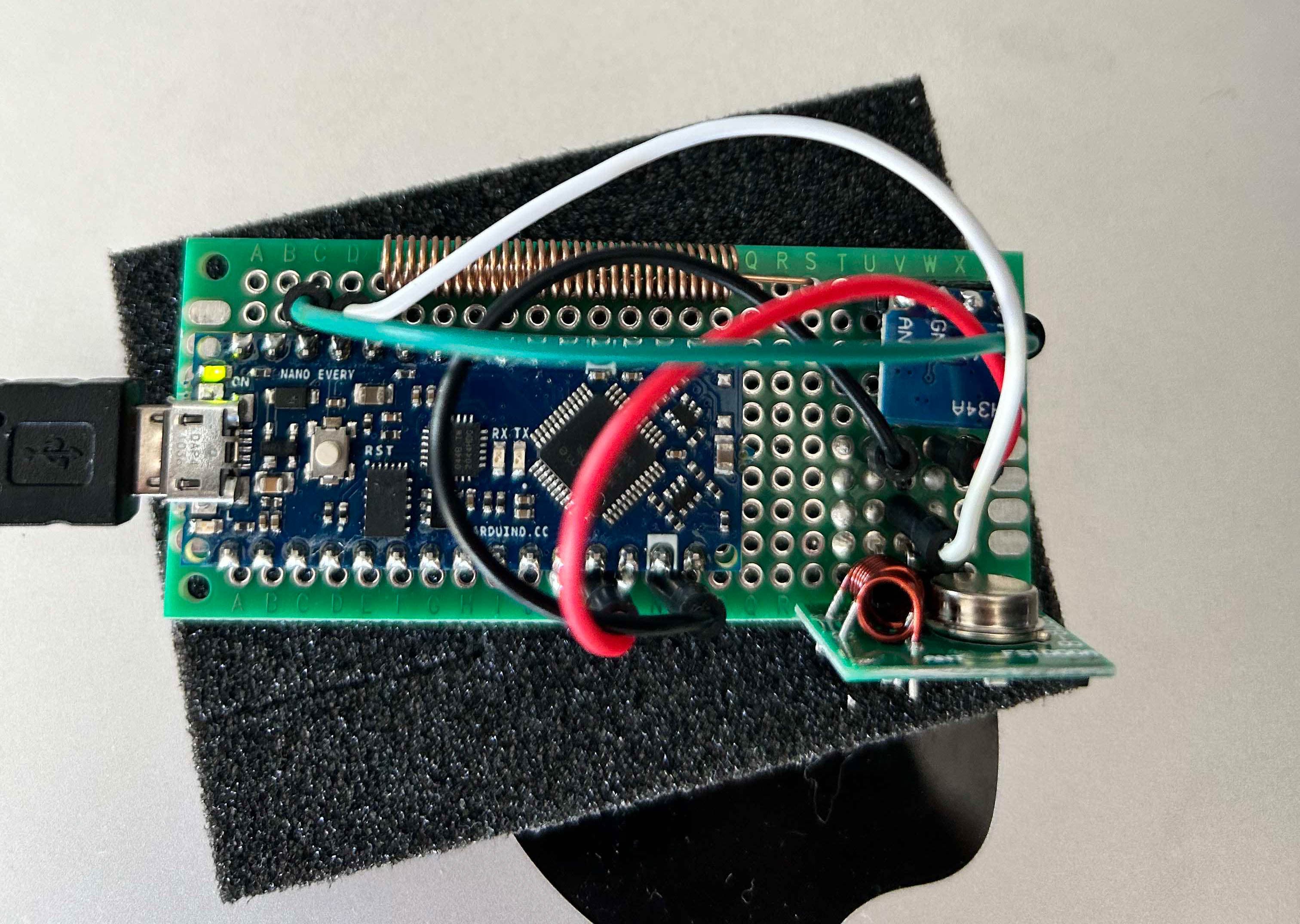
In my final setup, I added two transmitters, one for 315Mhz (you'll see the external antenna in the image above) and one for 433Mhz. I basically used the same setup as in the example above, but added the second transmitter on pin 9. Additionally, I added some code from homebridge-433-arduino to make it work with the homebridge plugin that I will use in the next chapter (this is basically writing a specific command to the serial port).
#include "RCSwitch.h"

// 315Mhz Pin
#define OUTPUT_315_PIN 10
// 433Mhz Pin
#define OUTPUT_433_PIN 9
// size of local message buffer
#define CHAR_BUFFER_SIZE 255

// Switches
RCSwitch switch_315 = RCSwitch();
RCSwitch switch_433 = RCSwitch();

char receivedChars[CHAR_BUFFER_SIZE]; // an array to store the received data
boolean newData = false; // was a full new string received?
String dash = "/";

void setup() {
  Serial.begin(9600);
  Serial.setTimeout(100);

  // Setup 315Mhz
  switch_315.enableTransmit(OUTPUT_315_PIN);
  switch_315.setRepeatTransmit(3);

  // Setup 433Mhz
  switch_433.enableTransmit(OUTPUT_433_PIN);
  switch_433.setRepeatTransmit(3);
}

// TODO: Not connected yet
void receiveRcData() {}

void receiveSerialData() {
  static byte ndx = 0;
  char endMarker = '\n';
  char rc;
  if (Serial.available() > 0) {
    rc = Serial.read();
    if (rc != endMarker) {
      receivedChars[ndx] = rc;
      ndx++;
      if (ndx >= CHAR_BUFFER_SIZE) {
        ndx = CHAR_BUFFER_SIZE - 1;
      }
    }
    else {
      receivedChars[ndx] = '\0'; // terminate the string
      ndx = 0;
      newData = true;
    }
  }
}

// gets the values from a string formatted like 123456/123
// e.g. 7819712/270/13 for the light
// e.g. 6842808/350/1 for the screen
String getValue(String data, char separator, int index) {
  int found = 0;
  int strIndex[] = {0, -1};
  int maxIndex = data.length()-1;
  for(int i=0; i<=maxIndex && found<=index; i++){
    if(data.charAt(i)==separator || i==maxIndex){
      found++;
      strIndex[0] = strIndex[1]+1;
      strIndex[1] = (i == maxIndex) ? i+1 : i;
    }
  }
  return found>index ? data.substring(strIndex[0], strIndex[1]) : "";
}

void sendRcData() {
  if (newData == true) {
    long value = getValue(receivedChars, '/', 0).toInt();
    long pulse = getValue(receivedChars, '/', 1).toInt();
    long protocol = getValue(receivedChars, '/', 2).toInt();
    if(protocol==0) protocol = 1;

    // Hardcoded mapping for now
    if (protocol == 1) {
      switch_433.setProtocol(protocol);
      switch_433.setPulseLength(pulse);
      switch_433.send(value, 24);
    } else {
      // Custom value for the ring
      switch_315.setProtocol(protocol);
      switch_315.setPulseLength(pulse);
      if (value == 1000) {
        // 25% brightness
        switch_315.send(7819715, 24);
        delay(10);
        // ON/OFF
        switch_315.send(7819712, 24);
      } else {
        switch_315.send(value, 24);
      }
    }

    Serial.println("OK");
    newData = false;
  }
}

void loop() {
  receiveSerialData();
  sendRcData();
  receiveRcData();
}
Note that I added a custom command with the value 1000 in the code because the light installation I was using didnt' have a dedicated on and off switch, but a single one that toggled the light. So in order to turn it off, I'm briefly turning it on and then off again to make sure its really off.
Connecting to Homekit
I'm using Homebridge internally to connect my arduino to Homekit, specifically this plugin. This should work with the code above out of the box, with a minor modification. As I am not using switches but a single "press" button (fire-and-forget), I had to modify the button component a little to make it work with what I wanted to do.
I added the following snippet to the constructor of ArduinoButtonAccessory.
self.service.getCharacteristic(Characteristic.On).on(
    "set",
    function (state, cb) {
      self.currentState = state;
      if (state) {
        const out = getSendObject(self.sw, false);
        self.transceiver.send(out);
        self.log("Sent on code for %s", self.sw.name);
        setTimeout(this.resetButton.bind(this), 1000);
      }
      cb(null);
    }.bind(self)
  );
This will essentially send out the command from the definition in the config file, and then reset the button after one second.
Here is an example of the config:
{
    "name": "Arduino RF",
    "serial_port": "/dev/cu.usbmodem14101",
    "platform": "ArduinoRCSwitch",
    "buttons": [
        {
            "name": "Screen Stop",
            "code": 6842808,
            "pulse": 350,
            "protocol": 1
        }
    ]
}
Final result
Here is a video of the final result.
Crazy how much work goes into controlling a simple light :). Of course I could have just bought a Homekit compatible light dimmer, but where's the fun in that?
Links
These articles and links helped me a great deal in writing this article: